Digital decoders for accessories (signals, points and whatever else is mounted on the model railway) need two things to work: Power to supply their circuit, and instructions from the DCC command station to understand what they are supposed to do.
In Helvest decoders, these two functions are performed by default by the same DCC wires: The unit receives both the power to operate and the commands from them, just as the locomotives do. This is the simplest and fastest connection, and for most layouts it is also the best. That is why Helvest decoders have this configuration as standard.
On Helvest accessory decoders, the DCC cables connected to the terminal of the HP100 provide both the power supply and the DCC instructions at the same time.
For very large model railways, it may make sense to separate the two functions. Each decoder alone consumes very little power, but in systems with dozens of decoders and hundreds of turnouts or signals, the total power requirement may no longer be negligible, and it may be preferable to use the DCC only for control and power the decoder with another power source.
This has the advantage of reducing the power requirement from the control unit (which is only a problem for very large systems, as we said). The disadvantage is obvious: an additional power source must be installed in the system.
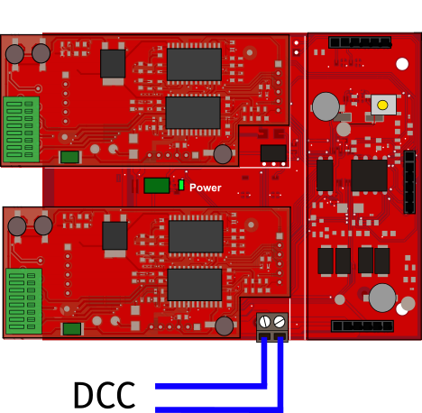
With the separate power supply you divide the inputs: The DCC signal only gives instructions (blue cables), another power source supplies the power to the decoder (red cables).
Modify the decoders to be powered separately
Helvest decoders can be modified for an external power supply with a minimum of craftsmanship to carry out a very simple soldering process.
The process will be done on the DCC100 module. The conversion is irreversible, i.e. you cannot reverse the module back into a DCC powering. However, if you want to restore the decoder to its original condition, you can simply replace the DCC100 module with a new one for a few euros.
This work refers to the DCC100 module. The modification is made on the right side in the picture.
Also note that the described modification will void the warranty.
What you need: A Helvest decoder consisting of HP100 motherboard, DCC100 module and one or two layout modules of your choice.
You will also need a soldering iron, solder, a screw terminal block with 5mm pitch, and wire cutters.
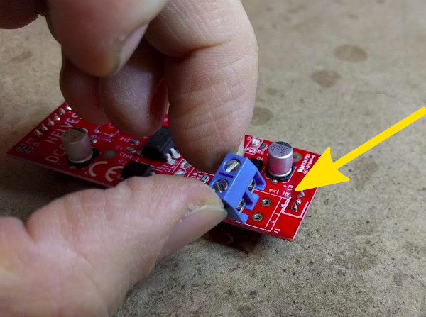
There are only two things to do. First you cut off the two PINs of the DCC 100 as shown in the picture. These are located at the position visible in the picture, near the pad to which the J1 screw terminal is soldered, and are highlighted by a white mark.
The PINs you must cut are marked by the yellow arrow.
Once you have found these two PINs, you need to cut them off at the base as shown in the picture. Of course, it is essential that you make sure they are the correct ones, otherwise your DCC100 will stop working.
Both Pins are cut at their base.
Once this is done, you need to position the terminal in the appropriate place as shown in the photo. No mistakes can be made here as this is the only slot that will accommodate it.
The connector must be placed in the housing marked by the arrow.
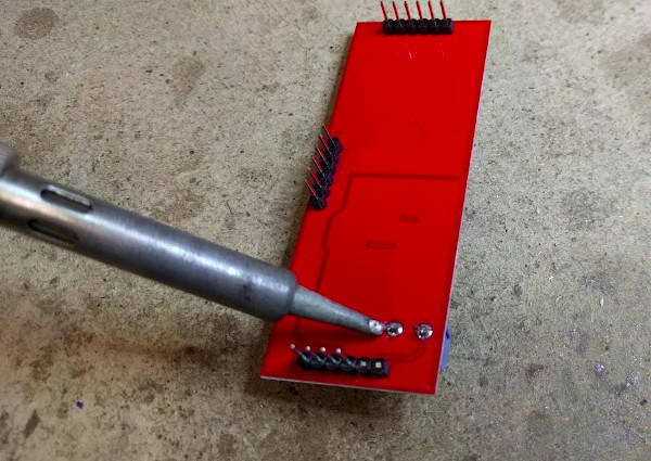
Solder in the contact pins and the conversion is complete.
The contacts are soldered on from below. You can also see the two cut header pins.
The new terminal is ready.
Electric connections
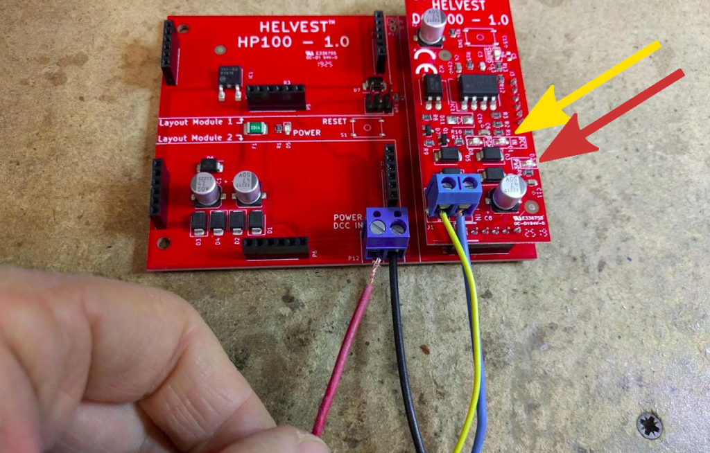
The DCC must be connected to the terminal you just soldered, as shown by the yellow and blue wires in the picture.
The DCC cables will be connected to the new placed terminal.
The power supply of the decoder should be connected to the terminal of the HP100, like the red and black wires in the picture. The power supply must be between 7 and 20 V DC or between 7 and 20 V AC. To operate turnouts, at least 12-15V must be supplied (depending on the type of motors).
There are two green LEDs on the DCC100 board: one indicates that the DCC is connected (the one with the yellow arrow in the picture, marked DCC IN) and the other indicates the board is powered (the one with the red arrow, marked PWR). Please check that both are lit on when you turn on both the power supply and DCC.
The power supply cables will be connected to the HP100 terminal.
Your decoder is ready. If you want to program the modified decoder, you must keep it powered. To do this, connect the programming wires coming from the controller to the DCC connector (yellow and blue wires in the photo), while power must be supplied to the HP100 in the mode you have chosen.
Our website uses cookies to make your browsing experience better. By using our site you agree to our use of cookies. AcceptSettingsRead More
Privacy & Cookies Policy
Privacy Overview
This website uses cookies to improve your experience while you navigate through the website. Out of these, the cookies that are categorized as necessary are stored on your browser as they are essential for the working of basic functionalities of the website. We also use third-party cookies that help us analyze and understand how you use this website. These cookies will be stored in your browser only with your consent. You also have the option to opt-out of these cookies. But opting out of some of these cookies may affect your browsing experience.
Necessary cookies are absolutely essential for the website to function properly. This category only includes cookies that ensures basic functionalities and security features of the website. These cookies do not store any personal information.