The NET module handles communication with the digital control unit, the computer, or the rest of the layout.
Two protocols are currently available:
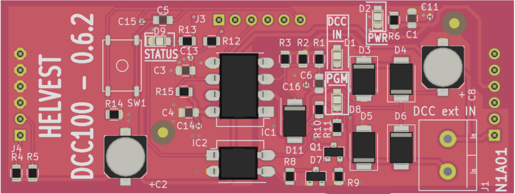
DCC: it is the traditional system, with which the layout is managed via the digital control unit. (DCC100 and DCC100-E modules)
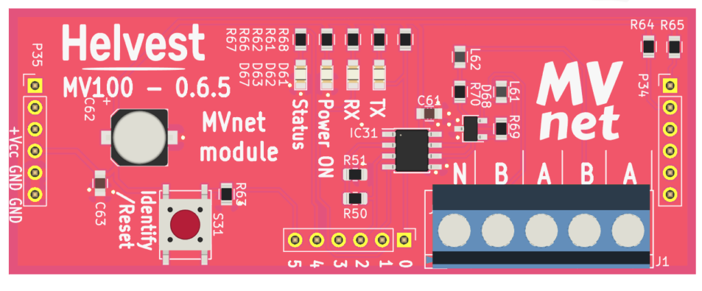
MVnet: it is the innovative network developed by Helvest. This network is designed for two possible uses: to manage the layout with the computer or to manage automations autonomously, without a control unit.
The modules available are: