The “Tortoise” and “Cobalt” switch motors are conceptually similar and give a very realistic needle movement. Let’s see how easy they can be driven with the DCC Helvest FleX accessory decoder.
Material selection and preparation
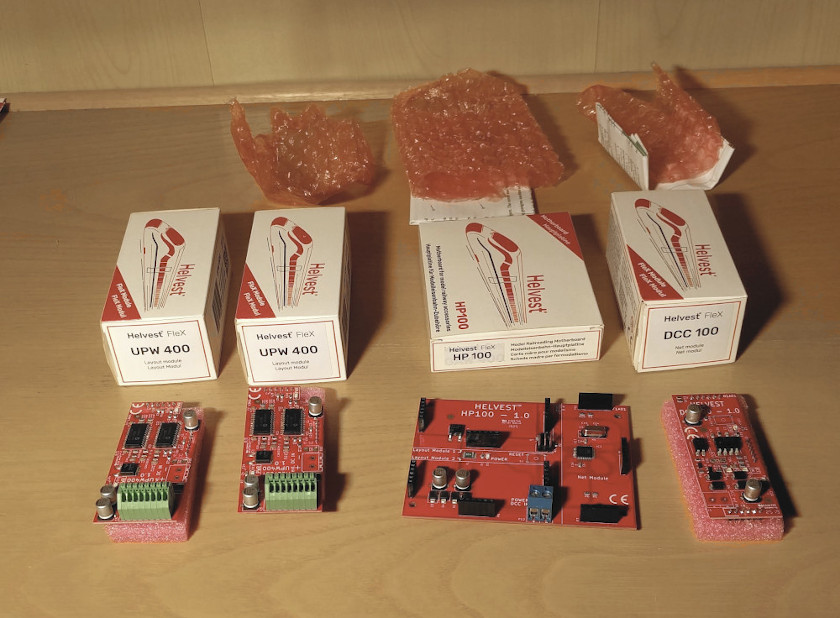
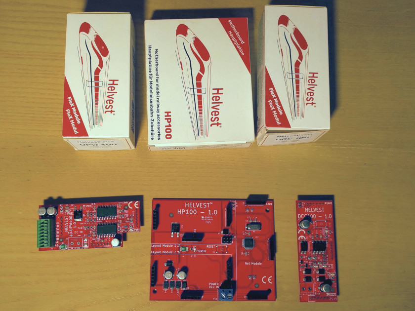
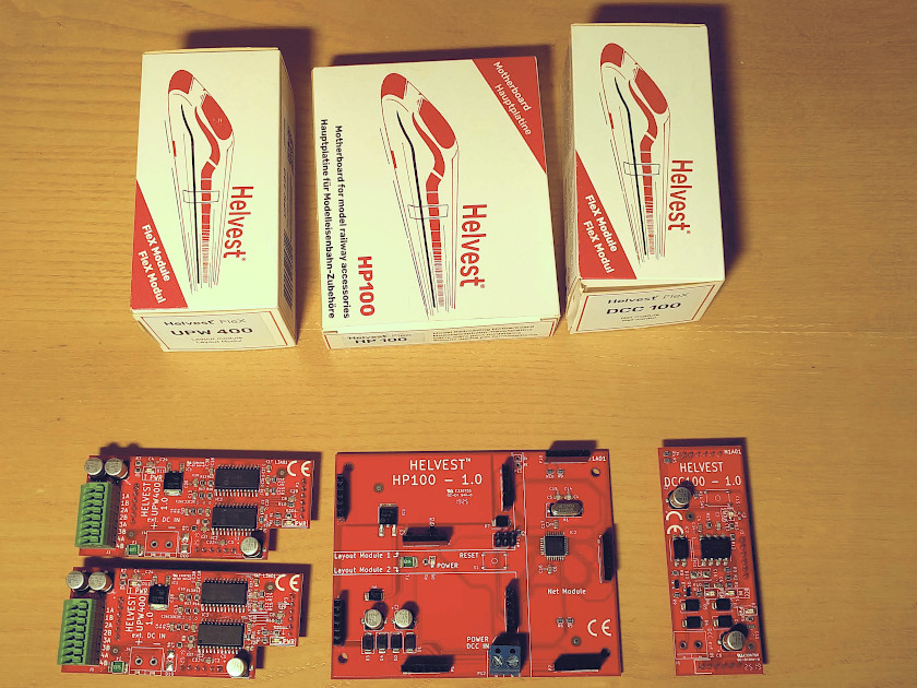
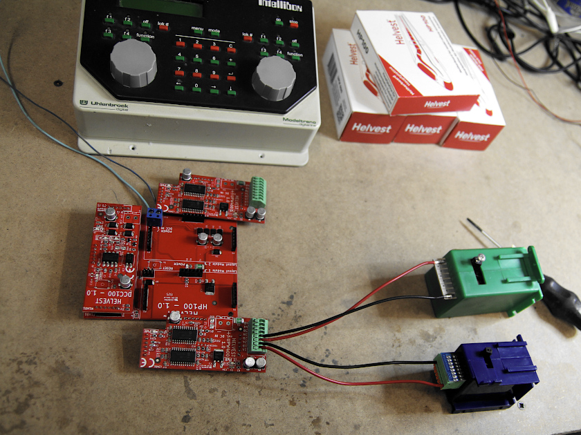
In addition to the motors, to assemble the decoder you will need an HP100 motherboard, a DCC100 net-board, and UPW400 turnouts modules.
From left to right: two UPW400 modules, the HP100 and the DCC100
Each UPW400 module drives up to four turnouts, then:
– for a decoder with up to four turnout outputs you need one UPW400 module
– for a decoder with up to eight turnout outputs you need two UPW400 modules.
If you have more than eight turnouts, you are lucky because you have a very nice station, and you will need more than one decoder.
Material for a 4-output decoder
Material for a 8-output decoder
Identifying contacts on the motors
As we said, Tortoise motors and Cobalt motors are based on the same technology. It is therefore necessary to identify two contacts that will be inserted in terminals A and B of the UPW400.
These two motors are not particularly friendly in connection management. In both of them there is absolutely nothing written about the meaning of the many contacts.
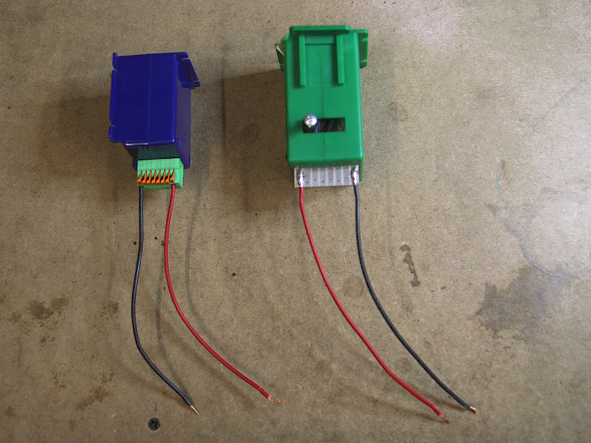
Talking about the Tortoise (the green one in the picture) the contacts that move the motor are at both ends. You can buy complicated plugs to insert, we have preferred to solder two wires as you can see in the picture.
For the Cobalt, the situation is complicated because the contacts are not in the same position in all the motor series. In our example the contacts are equally at the ends, but please check the instructions on yours!
Once you have figured out which contacts you need, connect or solder two wires. We have soldered a red wire and a black one, but it is not necessary to distinguish the two contacts, you can also use two identical wires.
Left: “Cobalt” motor, right: “Tortoise” motor
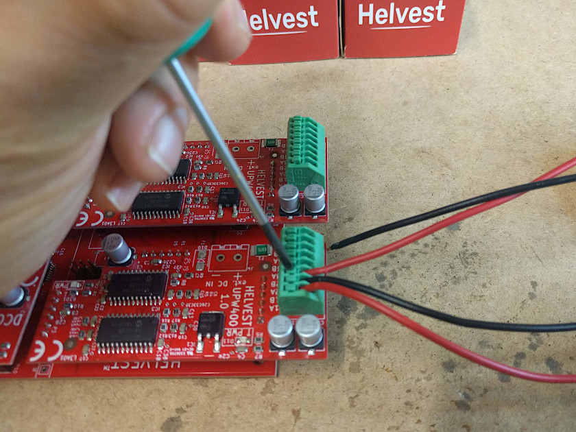
The two wires must be connected to the UPW400 outputs, obviously to two outputs A and B marked with the same number (1A and 1B, or 2A and 2B, as in the example).
Connection of the turnout outputs: For each motor one cable goes to an output A, the other to the corresponding output B.
In the example the Cobalt wires are connected in 1A and 1B and the Tortoise wires in 2A and 2B.
The connection is done. Since the operation of these motors is slow, we recommend to increase the switching time a little as explained in the manual.
Should you need to program the decoder, please remember to disconnect the Layout modules!
When you program the Helvest decoders, please do not forget to temporary disconnect the “layout” modules
After programming, reinsert the Layout Modules, connect the DCC, and enjoy your layout!
Our website uses cookies to make your browsing experience better. By using our site you agree to our use of cookies. AcceptSettingsRead More
Privacy & Cookies Policy
Privacy Overview
This website uses cookies to improve your experience while you navigate through the website. Out of these, the cookies that are categorized as necessary are stored on your browser as they are essential for the working of basic functionalities of the website. We also use third-party cookies that help us analyze and understand how you use this website. These cookies will be stored in your browser only with your consent. You also have the option to opt-out of these cookies. But opting out of some of these cookies may affect your browsing experience.
Necessary cookies are absolutely essential for the website to function properly. This category only includes cookies that ensures basic functionalities and security features of the website. These cookies do not store any personal information.