In a previous article, we explained how it was possible to operate N-scale Kato turnouts using UPW400 modules.
In the Japanese manufacturer’s range, there is one product that is rather widely used, the dual communication cod.20-210, which is of interest to some of our customers.
This type of switch is designed for analogue use and parallels four double coils. In addition, the manufacturer does not indicate the current consumption during switching in the instructions, so it is not easy to understand whether it can be managed with Helvest modules or not. Which is why we’ve been working on it in our labs.
Like its single-coil counterparts, this device also needs to work with the UPW400 module, but to do this you need to separate the four coils so that they can be powered in pairs, which is a fairly straightforward operation. Here’s how to do it:
1. First, remove the two metal plates that protect the mechanism by turning the screws. The plates are held in place at the ends by small pins, but all you have to do is bend them a little by levering in the central part for the pins to come out and the device to open.
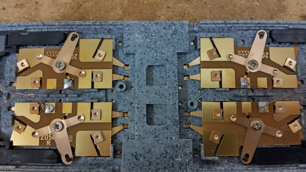
2 After opening, the wiring is clearly visible. The coils are soldered together in pairs on each side. The modification consists of desoldering the wire which connects the two sections (the red one between the two orange arrows and the black one between the two white arrows).
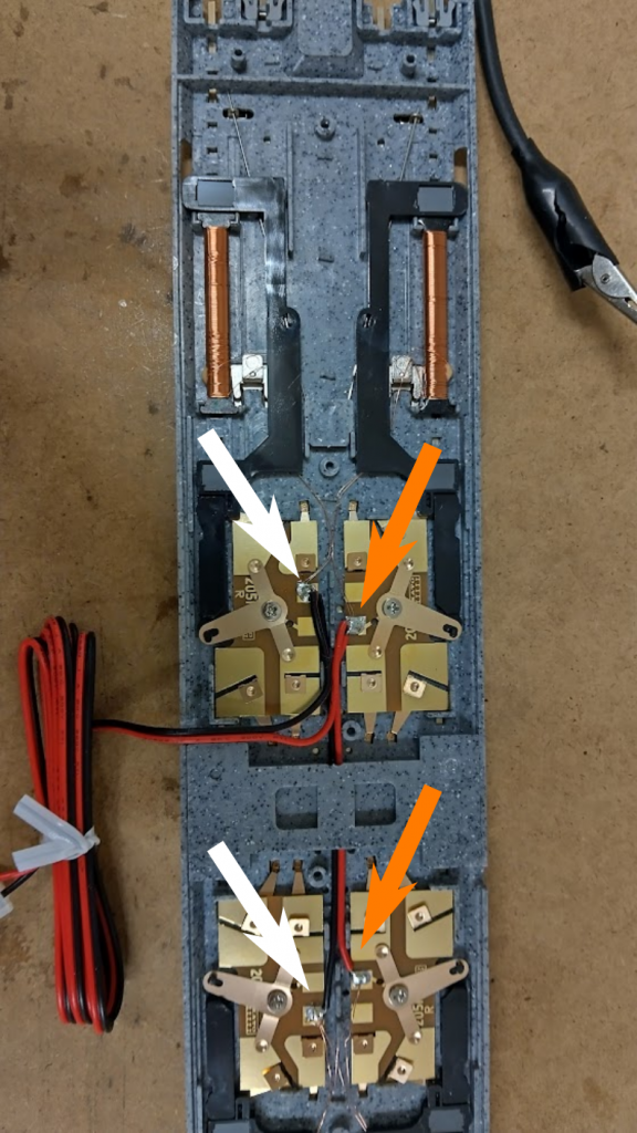
3. after desoldering the wire, simply leave the two existing output wires on one side and solder a red wire to one pole and a black wire to the other so that the connections are the same on both sides. It is important that you keep the previous colours and do not swap them so that there is no confusion in the connections.
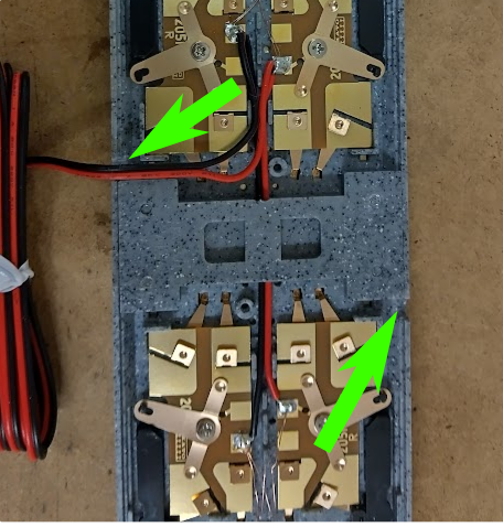
4. the pair of new wires that you have just soldered must be routed outwards into the corresponding groove that is symmetrical to the one on the other side (green arrows).
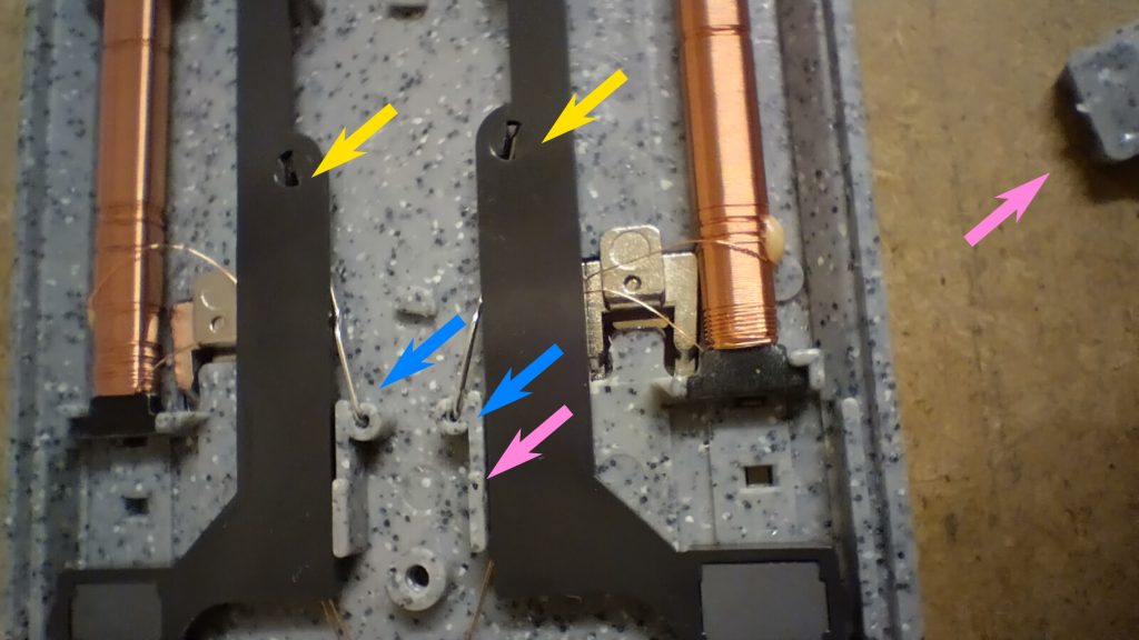
5. the four springs that hold the switch in place may detach when you manipulate the mechanism. It is very easy to put them back into position: On one side, they are attached to the corresponding small hole, as shown in the photo (yellow arrow). On the other side, they are inserted into a small hole under the blades (blue arrow). Finally, replace the plastic cover if it has moved (pink arrow).
6 The job is done. You just have to close everything again.
7. To make the electrical connections, place one of the two pairs of red and black wires into any A and B output of the UPW400, and the other pair into another output. Assign the same address to both outputs so that the entire device is operated by the same command, and check that all four turnouts are positioned the same way (for parallel routes or track switching). For other adjustments, simply handle them like a single Kato turnout.
* Third party’s trademark