Programming and addressing of accessories with DCC
Sometimes DCC does not make life easier for model railroaders (and sometimes some manufacturers don’t help too much, as we will see). An example is the way decoders for accessories are addressed, but don’t worry: Just clear your head and it will be easier!
Accessories are turnouts, signals, and everything is mounted on the layout. If you want to keep the undoubted advantages of digital management, they must be controlled by a decoder.
Addressing the decoder
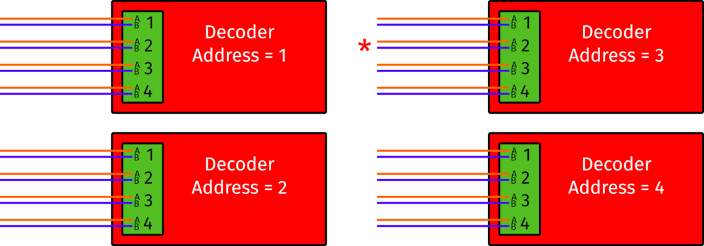
With this type of addressing, each decoder has its own address. Each decoder then has four outputs ( turnouts, signals or accessories), and each of them has a status (red/green, diverted/corrected track, etc.). Then, the control unit identifies the accessory by calling it with address and port. The diagram below shows four generic decoders addressed in this way, and for example, let’s suppose you call address 3 and port 2, it will be the output marked with an asterisk.
Each accessory is identified by the address of the decoder and its output. The asterisk marks the output 2 of the decoder 3. Each output has two states (A and B) corresponding to the movement of a switch or the lights of a signal.
How to address the Helvest decoder
Addressing a Helvest decoder with this method is very simple: each “Layout” module, which has four outputs, has its own address. So in DCC you have one address for the “Layout 1” module in CV1 and one for the “Layout 2” module in CV 35. The example illustrates how to address four “Layout” modules with addresses from 1 to 4 by applying the example above.
Application of the example to Helvest Decoder. The addresses are written in CV1 and CV35.
Addressing of outputs
The other option is to assign addresses directly to the outputs. Therefore you no longer use the decoder number + output from 1 to 4, but the accessories are directly assigned a progressive number. In the example, the output shown with an asterisk becomes the number 10.
With this method the decoder has no longer an address, but the outputs are directly “labelled” with a number
How to address the Helvest decoder outputs
Outputs can be individually addressed using the CV 120, 130, 140, 150 for the Layout 1 card and the CV 160, 170, 180, 190 for the Layout 2 card.
So, to configure the outputs as in the general diagram above, for Helvest decoders you assign CVs as in the following image:
Correspondence between the CVs of the Helvest decoder and its outputs.
Please be aware that if you program CV 1 or CV 35, the values are automatically reassigned to all individual outputs. For example, if you program CV 1 with a value of 3, the values are automatically assigned to the following CVs:
CV 120: 9
CV 130: 10
CV 140: 11
CV 150: 12
The matching between the board address and CV address, for the lower values, can be found in the DCC100 manual.
Calculate the output addresses from the board address
An interactive programming guide will soon be available on the site, but for now you can work out the calculation by downloading the following table: just enter the values of CV1 and CV35 and you will automatically obtain the values that will be programmed in CV 120 – 190.
If you like mathematics, you can calculate it yourself: calling “s” the address of the card, “p” the number of the port (from 1 to 4) , and “a” the address of the accessories, the formula to obtain the address is a = (s-1) x 4 + p.
What is written about the correlation between the two addressing methods, is valid for any accessory decoder that complies with DCC/NMRA standards.
Non compliant control units
Unfortunately, not all power stations scrupulously follow the same protocol.
For example, Roco* control units (Multimaus, Z21, etc.) use a slightly different protocol, so that each output address is increased by 4, and each board address is increased by 1 compared to the above values. For example, if you program the value 5 in CV1, the card will respond to address no. 6. Or by writing the value 25 in CV 140, output 3 will respond to address 29 (25 +4).
* The names indicated with an asterisk are registered trademarks of third parties and are the property of their respective owners.
Do you like this article? Please comment or ask questions inour Facebook page, like it or share!
Our website uses cookies to make your browsing experience better. By using our site you agree to our use of cookies. AcceptSettingsRead More
Privacy & Cookies Policy
Privacy Overview
This website uses cookies to improve your experience while you navigate through the website. Out of these, the cookies that are categorized as necessary are stored on your browser as they are essential for the working of basic functionalities of the website. We also use third-party cookies that help us analyze and understand how you use this website. These cookies will be stored in your browser only with your consent. You also have the option to opt-out of these cookies. But opting out of some of these cookies may affect your browsing experience.
Necessary cookies are absolutely essential for the website to function properly. This category only includes cookies that ensures basic functionalities and security features of the website. These cookies do not store any personal information.