Why delay the activation of devices on your model railway layout
When setting up automation, it can sometimes be useful for two devices to be activated a few seconds apart.
Typical examples include:
– A slow-motion turnout motor moves the point blade, and a relay gives a train clearance. The relay must only activate after the turnout has completed its motion.
– A signal turns green (“clear”) and a relay starts the train. Here too, a short delay can improve realism.
Timing control in the Helvest GAW400 and UPW400 modules
In den genannten Beispielen ist die beste Kombination zur Steuerung der Gleisspannung ein GBR40-In the examples above, the best combination to manage track power is to use a GBR40 relay with a GAW400 module, regardless of whether you’re using DCC, MVnet managed, or MVnet unmanaged.
The GAW400 module includes timing for its outputs, which is very useful for these situations. The GAW400 (together with the UPW400 for slow two-wire motors) has some key features:
- Sequential output activation – If two outputs with addresses 3 and 4 are on the same module and are triggered in rapid succession, the motor on address 3 will be activated first. Only after that movement is completed will the motor on address 4 activate. If the order is reversed (4 then 3), the activation follows that order too.
- Sequential activation with the same address – If two outputs are assigned the same address (e.g. address 5), they are still activated in order, based on output number from lowest to highest.
Example: output 1A with address 5 + output 2A with address 5 → when address 5 is triggered, output 1A activates first, followed by 2A.
This sequential behavior only applies when both outputs are on the same module. If address 5 is assigned to outputs on different modules, both will activate simultaneously.
How to delay output activation
With the informations above, it is easy to configure outputs to trigger in sequence:
Example 1: Activate a relay only after a turnout has moved (both on GAW400)
- Assign the same address (e.g. 5) to both the turnout motor and the relay.
- Connect the turnout to a lower-numbered output (e.g. 1A) and the relay to a higher one (e.g. 2A).
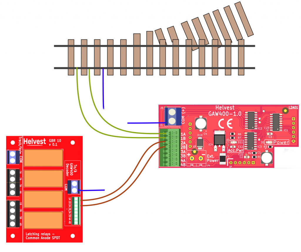
By assigning the same address, the turnout (points) is activated first, and then the relay, because the turnout is on a lower-numbered output (1) and the relay is on a higher-numbered output (2).
The relay will activate only after the turnout finishes moving.
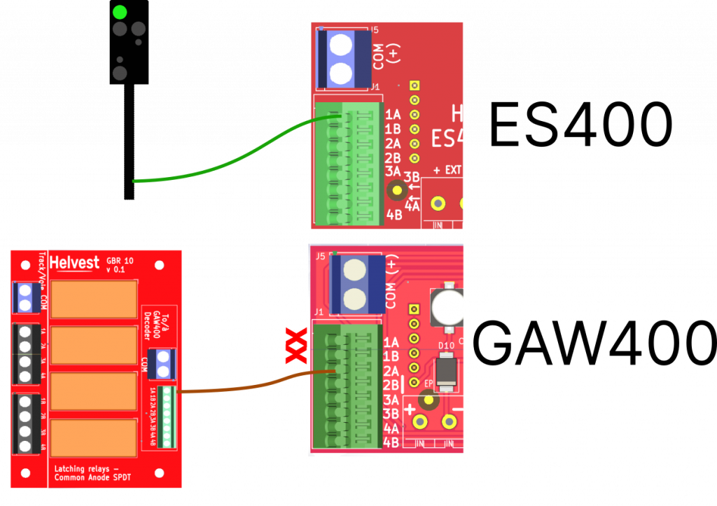
Example 2: Trigger a relay to start a train a few seconds after setting a signal (ES400 + GAW400)
In this case, two modules are needed: an ES400 module for the signal and a GAW400 module for the relay.
The signal can be connected to any output of the ES400. The relay must be connected to the GAW400, leaving a lower-numbered output free. For example, the relay can be connected to output 2A, while 1A remains unused.
As in the previous case, all outputs (signal, relay, unused output) must be assigned the same address (we will continue to use address 5 as in the example).
For the unused output (1A in the example), a desired delay time can be programmed:
- In the MVnet system, by adjusting the switching time in LocHaus.
- In DCC operation, by setting the corresponding CV value. The delay can be set up to approximately 5 seconds. In the example, we will set it to 3 seconds.
This way, the closing of the relay is delayed by a few seconds after the signal changes – a simple solution without complex additional circuitry.
If all outputs have the same address, output 1A of the ES400 module is activated at the same time as 1A of the GAW400. The relay connected to output 2A is activated only after that.
For those interested in how it works, here’s the detailed process:
Activation of address 5:
- The ES400 immediately switches the signal.
- The GAW400 activates the first output (1A) for the set time (3 seconds in the example). Since this output is not occupied, this creates a waiting period.
- After the time expires, the second output (2A) is activated, which switches the relay.
This simple trick allows you to easily delay the train’s start, matching the signal switching to green.
A flexible system
These are just examples. Once you understand the logic, you can use these techniques to control your devices in sequence or with delays—however you like. And if you’d like to share your own ideas or applications, we’d be happy to publish them for fellow readers of our Journal!