Should we be concerned about the polarisation of switch coils?
A subject that sometimes comes up when talking about point coils is that of polarisation.This obscure phenomenon worries modellers, often frightened by the “expert” friend who has sometimes heard it mentioned by another expert, and so on. This might sometimes discourage the more hesitant, who may end up maintaining all the limits of the analogue rather than taking this risk.But is this something to worry about? At Helvest, we have studied this phenomenon. In this article, we will discover that it is not at all worrying… provided you use the right decoder.
A little theoryWithout going into deep scientific and technical questions, let’s try to explain in a few lines (so without any pretension to rigour or exhaustiveness) what is the background of this fear.Coil motors are the oldest type of electric motorisation for turnouts. The principle is very simple: coils, or solenoids, create a magnetic field when a current flows through them. In a turnout motor, there are two coils, each producing a magnetic field in one direction and moving an iron core. The point blade is connected to this core, one coil moves it to one side and the other to the other.In analogue systems, the current flowing through these coils was an alternating current. In contrast, for almost all digital decoders, the current supplied to the coils is direct, as it is much easier (and therefore cheaper) for decoders to supply this type of current.In principle, care should be taken when direct rather than alternating current flows through a coil, for two reasons:Firstly, the current flowing through the coil is more intense (especially when the coil is at its end), which can damage it.Secondly, as the DC current always flows in the same direction (+ to -), the magnetic field is always oriented in the same way, which can lead to a risk of magnetisation of the metal core, which in the long run will react less to the provided pulse. When considering the polarisation of the motor, this is exactly what it is all about.

Diagram of the operation of a double coil. Feeding coil A, the core moves to the left. Feeding B, it moves to the right. A, B and COM in black are the three wires coming out of the device and connecting to the decoder.
The purposes of the EMW400 moduleThe EMW400 module has been designed to drive coils. But not just any coil: following our philosophy, we did not try to build the product “that does everything” (but maybe it does it badly). EMW400 drives coils designed, or adapted, for digital operation. Thus we were able to fine-tune both the output current, so that it was not too high, and the actuation time, avoiding keeping the coil energised long after the switch was turned.In doing so, we have taken all the necessary steps to ensure that the coil is subjected to as little stress as possible, and that it can therefore last for a long time without any problems. A product that operates any type of coil indiscriminately would have had to supply more current, and perhaps even longer, thus reducing the life of the motor.Our tests: millions of nights of peaceful sleep.But of course, theory is not enough: to really check whether this would happen, we subjected the coils to a severe test: many coils, of very different types and powered according to the manufacturer’s specifications, were subjected to continuous switching controlled by an EMW400 for days. This test was carried out on each coil that we list as suitable for the EMW400 on the website and in the documentation. Each coil had to perform between 500,000 and 1,200,000 switches, depending on the model.
Esempio di test condotto su un deviatoio Märklin*
The result? None of the coils tested showed any degradation in performance at the end of the test. And we chose to stop the test, because we consider that the objective has been achieved: the power supply provided by the EMW400 does not alter the solenoids, so we do not believe that continuing the test would have very different results. In any case, if you do the maths, it’s hardly possible that any of you have so much time to play with your miniature network that you end up with several million switches.Instead, we did a counter-test: we fed the Fleischmann 640000 coils with the wrong power supply, as shown in the figure. In fact, in this case, after about 50-60,000 switches, the coil started to work less well, and one of them even burned out. This confirms that a correct power supply is crucial for the longevity of the devices.
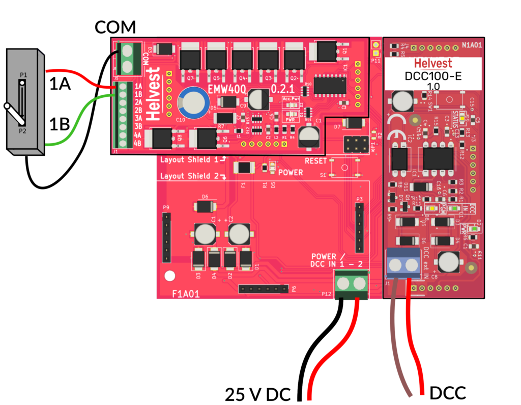
DON’T DO THIS! The Fleiscmann* 640000 turnout coil must operate between 14 and 18V. We powered them at 25V separately with a DCC100-E, as in the image. Effectively, we notice a drop in performance and a reduction in service life. By supplying 18V instead, this coil was as reliable and long-lived as all the others.
ConclusionAs is often the case with technological products, the problems that arise during use depend on the quality of the technology used. Coil polarisation is a phenomenon that exists, but with the right amount of carefully designed current, for the right amount of time, it does not occur.What our tests highlight is the importance of proper research and careful design. This is what distinguishes a high quality electronic product from a low quality one, and the effort we put into it so that you can enjoy it for a long time without worries.
* Names marked with an asterisk are registered trademarks of third parties and are the property of their respective owners.