What Does Powering the Frog Mean?
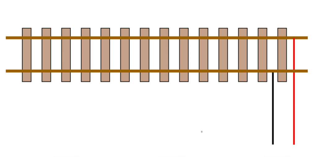
In two-rail model railway operation, as we know, the current for powering the trains is carried through the rails themselves. Regardless of whether the power supply is digital or analogue, one pole is connected to one rail (red wire) and the other pole to the opposite rail (black wire).
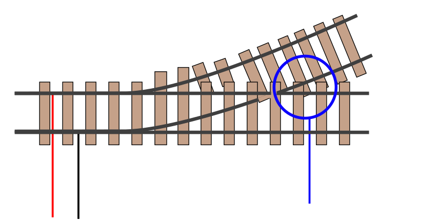
What Happens in Turnouts? In the area marked in blue, the polarity cannot remain the same: when the turnout is set for the straight route, it must be “red”, whereas when the turnout is thrown, it must be “black”. This point is called the frog of the turnout, and the power supply issue is solved in two possible ways:
- Non-powered frog. The section where the two rails meet is simply left without power, assuming that the locomotive will pick up current from another wheel. This makes current collection less reliable but simplifies the wiring.
- Powered frog. Depending on the turnout position, the polarity is switched from “red” to “black”.
How to Power the Frog
Many turnout motors include built-in contacts specifically for this function. But if such a contact is not available—as with certain solenoid switch machines, servo motors, or other cases—the solution is very simple and can be applied both to digital and analogue layouts.
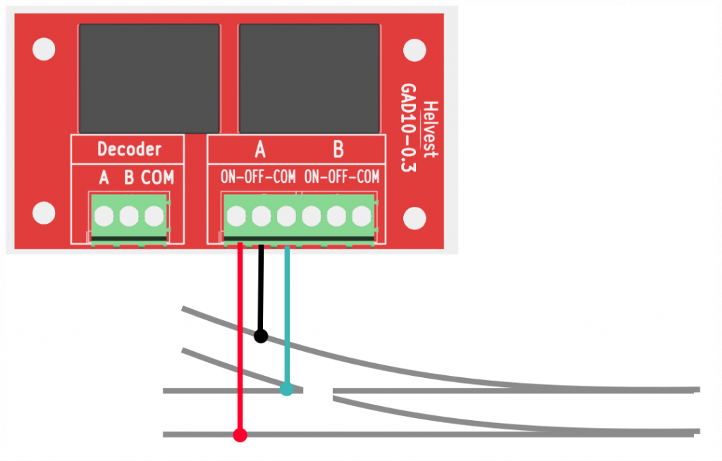
The Principle: The power supply to the frog (blue wire in the picture) is managed by a GAD10 relay, which provides either “black” or “red” power depending on the turnout position.
What you need
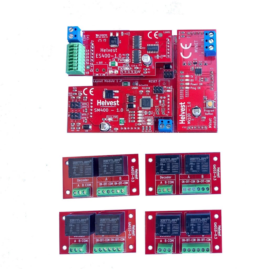
Here is the material required to assemble a Helvest digital decoder that allows you to control four turnouts with powered frogs:
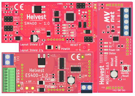
- 1 x HP100 (motherboard)
1 x communication module: DCC100, DCC100-E if you use traditional DCC, or MV100 if you use MVnet.
1 x ES400
1 x motor control module: SM400 (for servomotors), EMW400 (for electromagnetic motors), etc.
2 x GAD10 relay boards (2025 version or later). The 2025 version can be recognized by all the connection terminals being green instead of blue.
In the following examples, we will consider a servo motor decoder controlled via MVnet, but the procedure is identical for other types of motors or for DCC.
On the Helvest online shop you can find complete kits for this setup (control of 4 servomotors with frog polarization), in the section “Complete kits and accessory motors.” Naturally, the same setups—or customized combinations—are available through all sales channels.
How to assemble the decoder
Assemble the modules just like any other Helvest decoder (see figure) and connect the HP100, the MVnet or DCC network, and the turnouts according to the instructions. Leave only the ES400 module disconnected.0.
Connecting the relay to the decoder
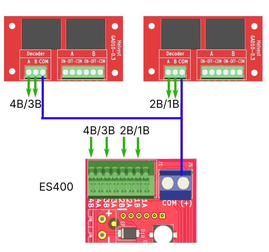
The relay terminal block labeled “Decoder” is, of course, the one that must be connected to the ES400 module of the decoder.
Connections must be made as follows:
COM contact → COM contact of the ES400 (blue wires in the image).
A and B contacts → 1B / 2B / 3B / 4B contacts of the ES400 (green arrows in the image).
It is CRUCIAL not to confuse the contacts at this stage, as this could damage the decoder!
Connecting turnouts to the relay
The rails must be connected to the terminals labeled A and B (see figure).
The contacts of these terminals are labeled ON–OFF–COM. ON and OFF must be connected to the rails (red and black), COM to the frog of the turnout.
The four turnouts are connected to the relays as shown in the figure, following the indicated order.
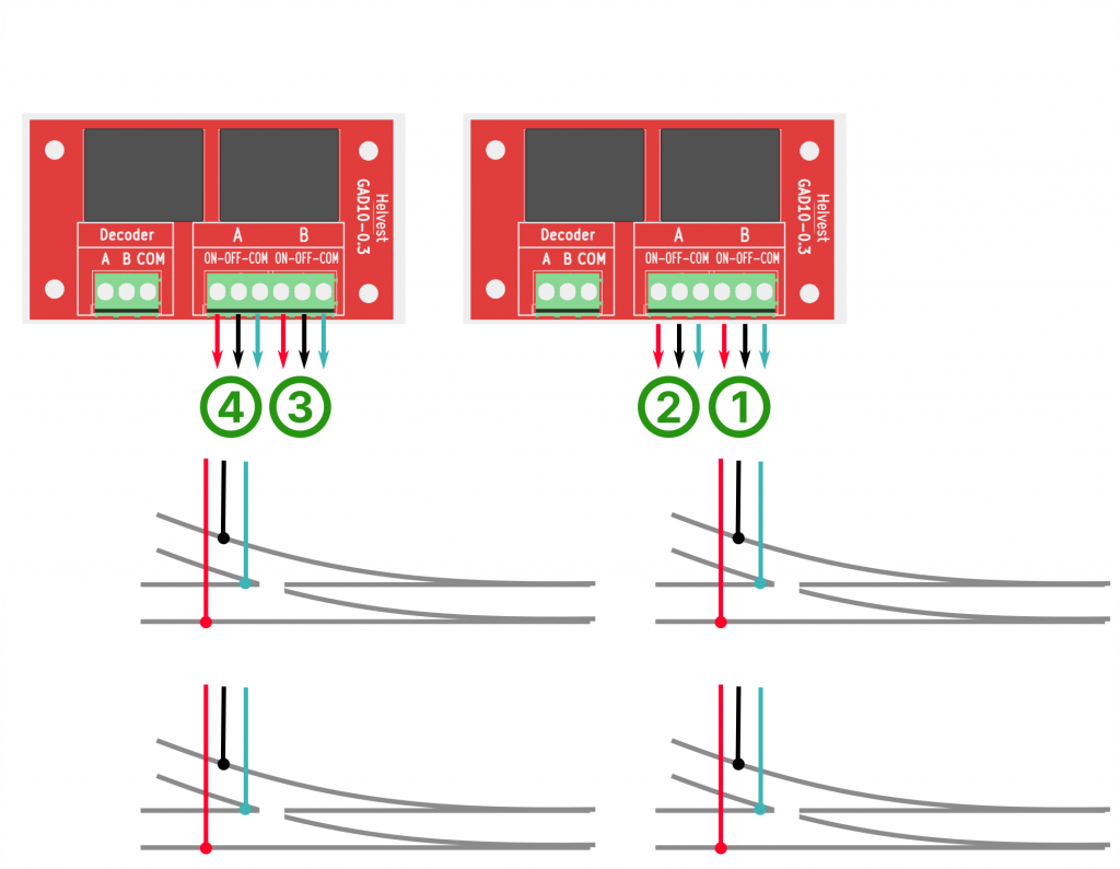
Important note: The position of the red and black wires on the ON and OFF terminals is not fixed: it depends on how you have mounted your turnout and your motor. Check with a tester (or other methods) that the frog polarity is correct. If it is not, simply swap the red and black wires on the ON/OFF terminals.
Programming
Programming is very simple: in DCC and MVnet, just assign the same address to the ES400 and to the turnout controlled by the other module. In this way, the relay will switch on or off depending on the turnout positions, assigning “red” polarity in one case and “black” polarity in the other.
And for an analogue layout?
The proposed solution also works for an analogue layout, whether it is controlled by a computer with LocHaus or in the traditional way using MVnet in unmanaged mode. Everything is done as described above, assigning the same address to the turnout and to the ES400.
To operate the turnout with a push button, even from a distance, simply assign the same address again to a decoder with a KB800 or KB800-L.
Alternatively, you can always control the GAD10 directly with a 12V DC voltage on the Decoder terminal, supplying COM with the positive pole and, using a switch, opening or closing the contact with the negative pole on terminals A or B.
Any further questions? Don’t hesitate to contact us via any of the available channels or on social media!