With the ES400 module, it’s possible to manage the most common signal aspects of German light signals in a simple and cost-effective manner. In this article, we will explore in detail how to do this.
Required Equipment and Programming
For managing the simplest signal aspects, the Helvest ES400 module is perfect, featuring four pairs of outputs. Each HP100 main board can accommodate two ES400 modules, giving us a total of eight pairs of lights to control. Each ES400 module has 4 ports with two outputs each, named 1A, 1B, 2A, 2B, 3A, 3B, 4A, and 4B, totaling 8 outputs. Activation of these outputs is done via the digital control unit or computer, according to the assigned addresses.
For programming via MVnet, assigning an address to each port is straightforward with the LocHaus application. For programming via DCC, you’ll need to input the desired values into the CVs specified in the diagram below, which also includes the default value. It’s essential to remove the modules from the layout when programming the decoder in DCC.
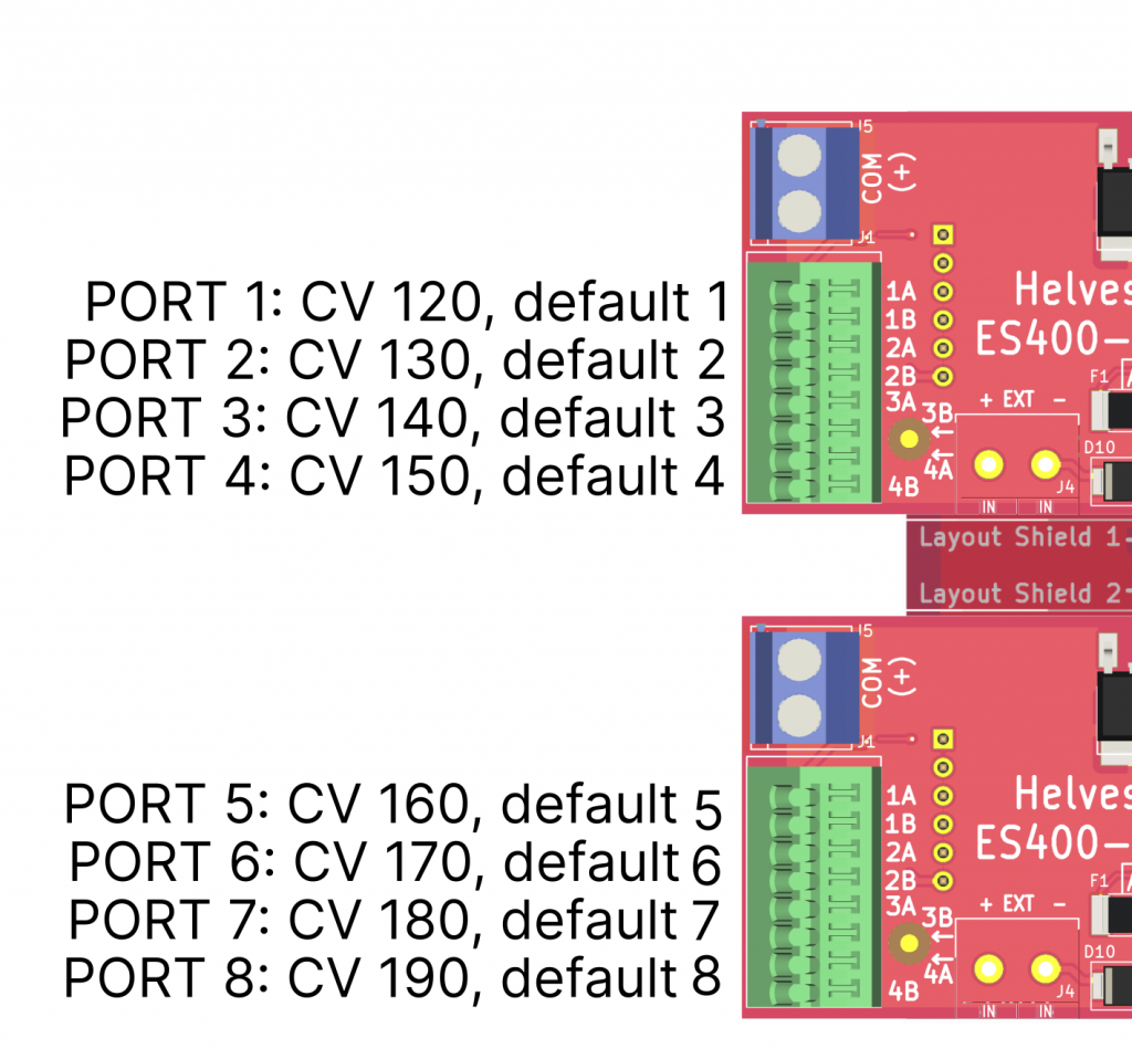
To change the port addresses using DCC programming, simply programme the corresponding CVs. Example: Port 6 has the standard address 6. If you want to change it to 34, you must write 34 in CV 160.
In the following examples, we will use the default addresses mentioned above in all cases. The ports and addresses provided are examples; you are free to choose a different port and/or address, adjusting the numbers accordingly to fit your chosen ports and addresses.
Which Signals Can I Control with the ES400?
This article is intended for managing German H/V light signals, but the principles outlined apply to all signals consisting of LEDs or small bulbs with a common anode and a wire to control each individual light. This includes signals from Viessmann*, Schneider*, and most signals available on the market. If you have any doubts, please contact us.
Connecting a Red/Green Signal (Hp0/Hp1) and Its Announcement
The simplest signal is the red/green one. According to the diagram below, connect the wire controlling the red LED to output 1A and the green one to output 1B. All these signals share a common wire, which should be connected to the blue COM terminal.
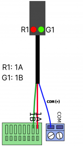
Addresses to select: 1A for Red (Hp0), 1B for Green (Hp1). Of course, if you choose different ports and/or addresses, the numbers above should be adjusted accordingly.
For the announcement signal, to indicate only announcements Vr0 and Vr1, the lights can be paired. Here, we assume you connect it to port 3 (A and B).
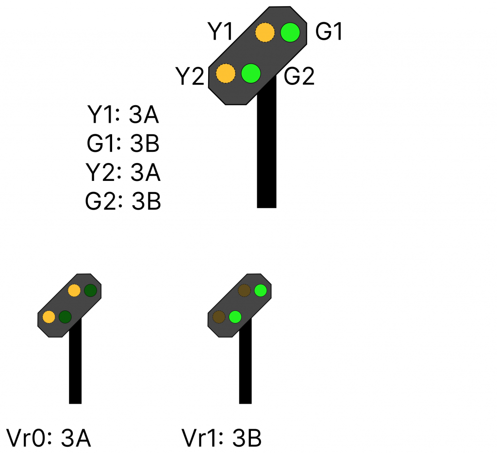
Here we have assumed that you connect it to port 3 (A and B).
Connecting a Red/Green/Yellow Signal
In this case, use one port for the red and green lights and an independent port for the yellow light, as shown in the diagram.
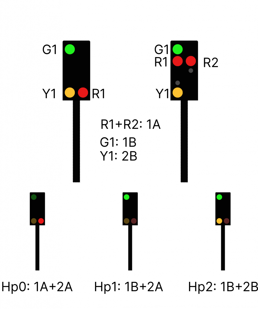
With a three-light signal, the combination of the different signal patterns is obtained by using two connections
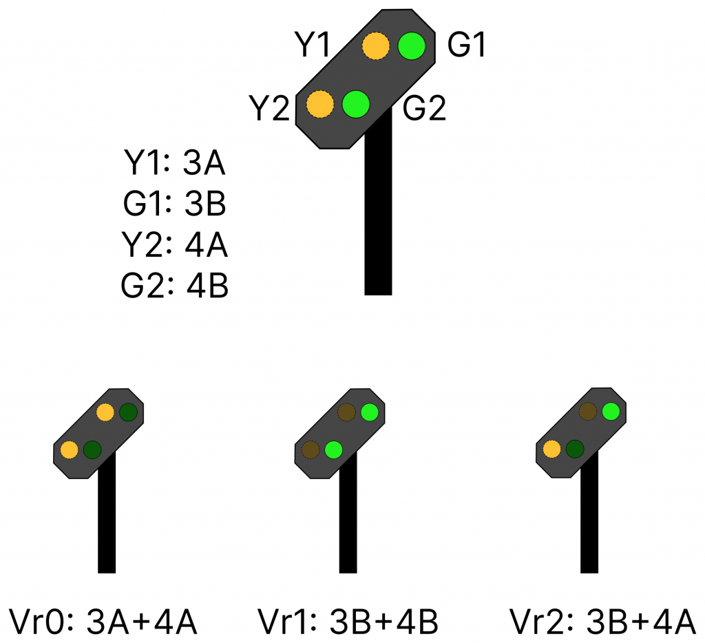
For the announcement signal, the four lights must be connected to two different ports to ensure independent activations.
These examples show how the most common signal patterns can be easily managed. Of course, it is also possible to control more complex signals with additional connections and tasks.
Names marked with an asterisk () are trademarks owned by third parties.