We have already published an article explaining the most common types of relays.
In this follow-up, we will look at some practical applications of the modules that Helvest is progressively making available.
GAR10 relays
As we have seen, a relay is a switch in which a small current, for example, from a decoder or an analog contact, opens or closes another electrical circuit (output), such as to activate an accessory or power a track.
The GAR10 module contains two monostable relays.
A monostable relay remains active only as long as a current is applied to its input, as shown in the diagram below (ON phase).
As soon as the current is interrupted, the relay deactivates, and the device it controls no longer receives power (OFF phase).
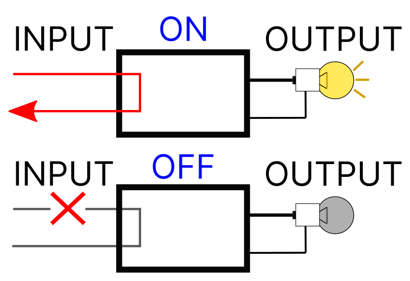
Another characteristic of a monostable relay is that it has no “memory.” When it is turned off or back on, or as soon as the current stops flowing, it always returns to its initial position.
What Applications Can Use a Monostable Relay?
We can identify two main categories of use:
- Activation by brief pulses (such as switching a turnout or a decoupler).
- Temporary activation of motors (such as powering a section of track, a light, or an accessory).
Connections of the GAR10 Module
Looking at Figure 2, Let’s Explore How to Use the Connectors:
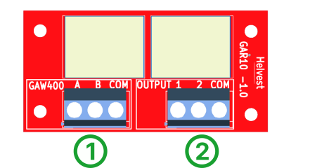
1. Connector No. 1: This connector controls the relays. It can be connected to a Helvest GAW400 module (for brief pulses) or an ES400 (for continuous pulses).
If you want to control it with another decoder or an analog command:
- COM: Insert the common positive pole at 12 V.
- A and B: Connect them to the negative pole to activate the relay.
2. Connector No. 2: This connector controls the output.
- COM: Insert the common current input.
- Outputs “1” and “2”: When you activate input “A” (via the decoder or manually in analog), output “1” is activated.When you activate input “B,” output “2” is activated.
Examples of Use
1. Connecting Old Turnouts or Electromagnetic Coils
Directly controlling electromagnetic coils or older turnouts designed for alternating current with a decoder is not recommended.
This can be harmful to both the decoder and the coils. In most cases, the decoder must deliver very high current peaks, which can damage its circuits. Moreover, the decoder generally provides a direct current, which is unsuitable for a coil designed for alternating current.
These issues do not arise with motors specifically designed for digital control (see here for more details), but for older coils, it is better to use a relay that simulates the press of a button. This effectively corresponds to the intended operation of such devices.
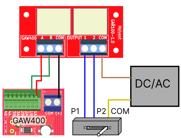
To connect an electromagnetic motor, follow these steps:
- You need a Helvest decoder equipped with a GAW400 (although the operation is also compatible with other decoders).
- Connect the relay to the decoder as shown in the figure. Of the two wires for alternating current coming from the transformer, one should be connected to the common terminal of the coil and the other to the COM terminal of the GAR10.
- The two wires from the coil, which switch the turnout between two positions, should be connected to terminals 1 and 2 of the GAR10.
2. Connecting Single Coils (e.g., Uncouplers or Other Devices)
Single coils operate in a conceptually similar way but differ in that, instead of having two wires to switch an accessory between two positions like a turnout, they have a single wire to activate the device when needed.
For these devices, the connection is similar to the previous case. However, you will only use one of the two outputs, A or B (e.g., A), from the decoder.
Important Note for These Devices:
When you activate the device by pressing the A button on your control panel, remember that the decoder will not reactivate the device if you press A again. You must reset it by pressing B.
To optimize the operation of certain accessories, it may be helpful to adjust the switching time.
For this:
- With MVnet, you can perform this operation graphically via LocHaus.
- If your decoder is DCC, you need to program the CV corresponding to the output (refer to the DCC100 module instructions).
3. Powering Tracks
A monostable relay can be used to power a track section or, more generally, a motor.
Usually, a bistable relay is used for such operations, but in certain cases, a monostable relay can also be practical.
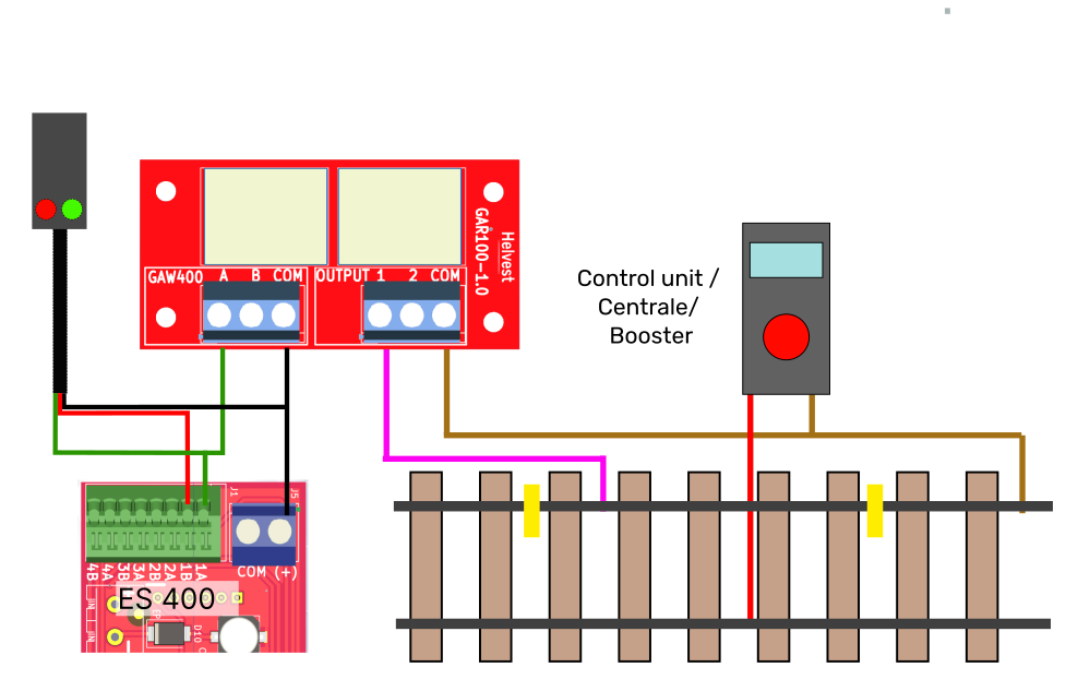
For this configuration the connection must be made as shown in the figure. The decoder will activate the relay (and thus the motor or train) when in position A and deactivate it when switching to position B.
An ES400 module is needed to control the decoder digitally, as a continuous pulse is required.
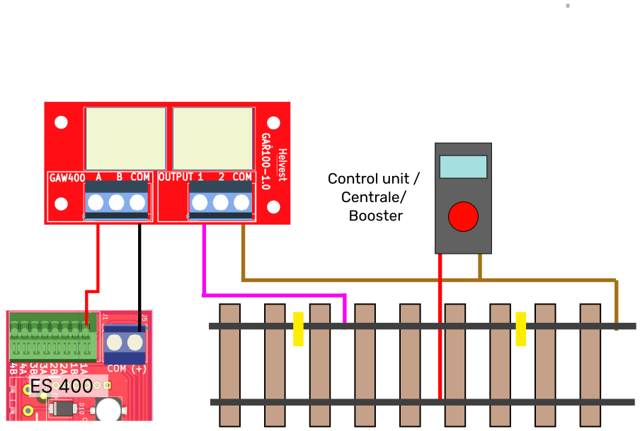
This connection enables power to be supplied to the section between the two yellow sections via the GAR10 board.
Input B and output 2, which are not used here, can be used to power another section.
Situations Where This Configuration May Be Preferred:
Temporary Contact Ensured: A bistable relay switches between two states (ON/OFF), both of which are stable—once activated, it remains on until a new operation occurs. A monostable relay, on the other hand, is normally off and only activates when it receives a pulse. This provides increased safety by preventing unintended power supply.
Reset on Restart: When the power is cut (e.g., when the layout is turned off), a monostable relay returns to the off state.
Synchronization with Signal Status: In this configuration, ideal with an ES400 module, track power can be synchronized with the signal status. If your LEDs draw no more than 100 mA (as is the case in most scenarios), you can connect the relay and the signal to the same output, simplifying wiring and reducing costs (see figure).
These are the most common uses, but of course, many others exist, thanks to the versatility of these indispensable small devices.